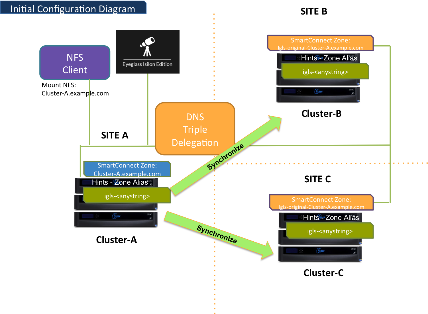
The following diagram displays the initial configuration / before failover for 3-sites Failover.
Site A: Primary Site
Site B: Secondary Site #1
Site C: Secondary Site #2
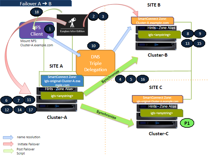
Failover A ⇒ B
The following diagram illustrates the workflow for failover from A to B. Take note step P1 (Preparation Step - prior to initiate Eyeglass Access Zone Failover) - refer to the procedure section for details.
Refer to this table for the list of the numbered steps shown in this diagram.
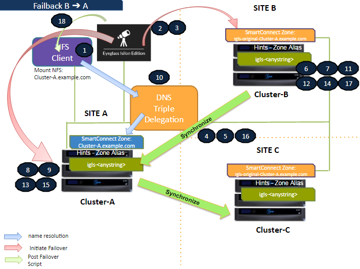
Failback B ⇒ A
The following diagram illustrates the workflow for failback from B to A. Refer to this table for the list of the numbered steps shown in this diagram.
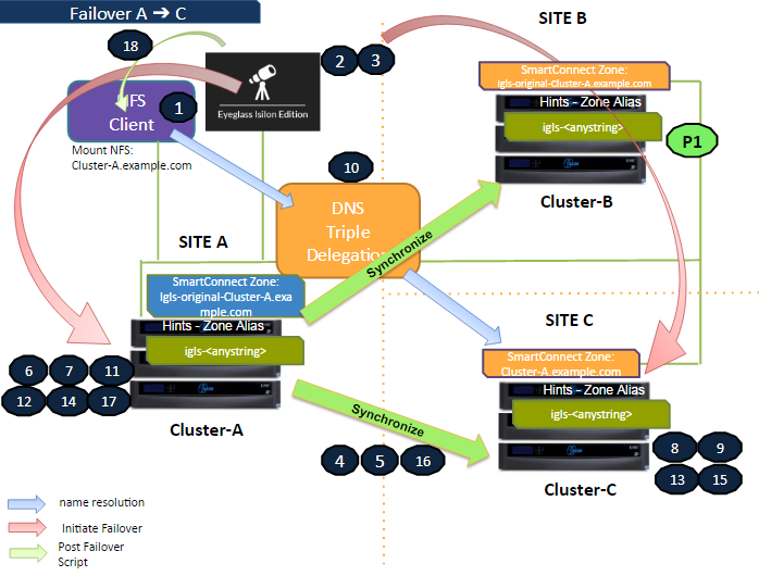
Failover A ⇒ C
The following diagram illustrates the workflow for failover from A to C. Take note step P1 (Preparation Step - prior to initiate Eyeglass Access Zone Failover) - refer to the procedure section for details.
Refer to this table for the list of the numbered steps shown in this diagram.
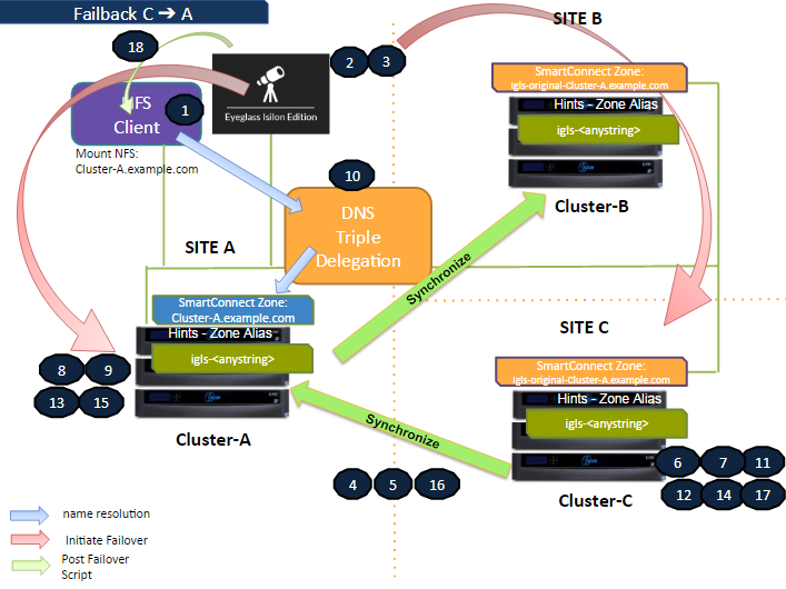
Failback C ⇒ A
The following diagram illustrates the workflow for failback from C to A. Refer to this table for the list of the numbered steps shown in this diagram.
Eyeglass Access Zone Failover Steps
This table lists the Eyeglass Access Zone Failover steps with numbers as shown in the above Failover diagrams.
No
Step
P1
Preparation.
Failover A ⇒ B: Ensure there is no existing Mirror Policies between C to A. If there is existing Mirror Policies between C to A, delete first, before initiate Failover from A to B.
Failover A ⇒ C: Ensure there is no existing Mirror Policies between B to A. If there is existing Mirror Policies between B to A, delete first, before initiate Failover from A to C.
1
Ensure that there is no live access to data
2
Begin Failover
3
Validation
4
Synchronize data
5
Synchronize configuration (shares/export/alias)
6
Change SmartConnect Zone on Source so not to resolve by Clients
7
Avoid SPN Collision
8
Move SmartConnect Zone to Target
9
Update SPN to allow for authentication against target
10
Repoint DNS to the Target Cluster - DNS Triple Delegation
11
Record schedule for SyncIQ policies being failed over
12
Prevent SyncIQ policies being failed over from running
13
Provide write access to data on target
14
Disable SyncIQ on source and make active on target
15
Set proper SyncIQ schedule on target
16
Synchronize quota(s)
17
Remove quotas on directories that are target of SyncIQ (PowerScale best practice)
18
Refresh session to pick up DNS change (use post failover script)
Eyeglass Access Zone Failback Steps
This table lists the Eyeglass Access Zone Failback steps with numbers as shown in the above Failback diagrams.
No
Step
1
Ensure that there is no live access to data
2
Begin Failback
3
Validation
4
Synchronize data
5
Synchronize configuration (shares/export/alias)
6
Change SmartConnect Zone on Source (Secondary Cluster) so not to resolve by Clients
7
Avoid SPN Collision
8
Move SmartConnect zone to Target (Primary Cluster)
9
Update SPN to allow for authentication against target
10
Repoint DNS to the Target Cluster - DNS Triple Delegation
11
Record schedule for SyncIQ policies being failed back
12
Prevent SyncIQ policies being failed back from running
13
Provide write access to data on target
14
Disable SyncIQ on source (Secondary Cluster) and make active on target (Primary Cluster)
15
Set proper SyncIQ schedule on target (Primary Cluster)
16
Synchronize quota(s)
17
Remove quotas on directories that are target of SyncIQ (on Secondary Cluster) (PowerScale best practice)
18
Refresh session to pick up DNS change (use post failover script)