Eyeglass All Product Installation and Upgrade Guides Publication
Mini-ECA Installation and Configuration to Enable Distributed Cluster Mode
Home
- Overview
- Requirements
- Firewall for Mini ECA
- Network Impact Calculation
- Deployment Diagram
- How to Deploy Mini-ECA VM's
- How to Configure Mini-ECA nodes to Join Central ECA cluster
- How to configure NFS mount on Mini-ECA
Overview
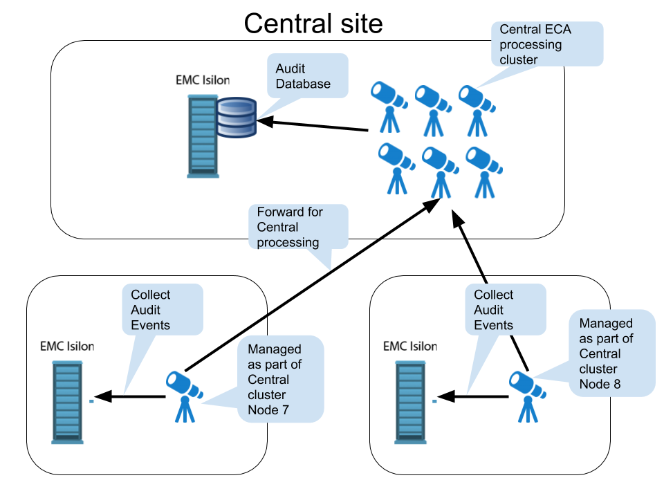
New in release 2.5.5 is mini-eca deployment mode that enables centralized security processing of cluster audit data. This reduces the cost and simplifies deployments with a large central analytics and database ECA cluster and distributed single VM or VM pairs at remote locations that collect audit data locally and forward to the central cluster for processing.
Requirements
- The latency between the main ECA cluster and the remote mini ECA's must be below a ping time of 80 ms. Anything over this may not be supported.
- The FSTAB method of mounting the cluster audit folder is required (see instructions below)
Firewall for Mini ECA
| Port | Direction | Comments |
| 22 ssh |
admin pc --> mini ECA | |
| 2181, 2888 TCP | ECA main cluster <-> mini eca | |
| 9092 , 9090 TCP | ECA main cluster <-> mini eca | |
| 5514 (TCP) as of 2.5.6 build 84 | mini ECA --> Eyeglass | |
| 443 (TCP) | mini ECA --> Eyeglass admin pc --> mini eca | |
NFS UDP/TCP port 111, TCP and UDP port 2049 and UDP 300 NFSv3 only | mini ECA --> cluster | |
| NTP (UDP) 123 | mini ECA --> NTP server | |
| DNS UDP 53 | mini ECA --> DNS server | |
| TCP port 5000 for node 1 ECA (during upgrades only) | all ECA and mini ECA --> node 1 main ECA cluster IP |
Network Impact Calculation
- To Calculate the bandwidth requriement requires knowing the audit event rate for the cluster.
- To get the audit event rate run this command to get disk operations average per PowerScale node
- isi statistics query current --nodes=all --stats=node.disk.xfers.rate.sum
- This command returns the average per node at the bottom of the results. Use this value in the calcuation below.
- Take the average per node and multiple by the number of nodes.
- example 2200 (average as reported with command above) * 7 (nodes) = 15,400. Divide this number by 1.83415365 (ratio of audit events to disk transfers). 15,400 / 1.83415365 = 8396 events per second
- Now use the calculation below to compute the network bandwith required to on average to forward events to the central site for processing.
- 5 Mbps of network traffic @ 1000 events/sec example 8396 events/sec ➗1000 * 5 Mbps = 40 Mbps
Deployment Diagram
How to Deploy Mini-ECA VM's
- Deploy the OVA as normal following ECA OVA deployment instructions
- Delete ECA node 2 and 3 for a single Mini-ECA deployment (NOTE: mini-ECA does support HA configurations and can operate with ECA nodes 1 and 2 , this would require only node 3 is deleted from the vApp)
- Done
How to Configure Mini-ECA nodes to Join Central ECA cluster
- Login to ECA Central node 1 as ecaadmin
- vim /opt/superna/eca/eca-env-common.conf
-
Add additional ECA nodes , add a line for each mini-ECA at each remote site and increase the node ID for each new line
- export ECA_LOCATION_NODE_7=x.x.x.x
-
run 'ecactl components configure-nodes' to add mini for passwordless ssh
-
vi /opt/superna/eca/data/common/neOverrides.json to add clusters for specific nodes copy the text below and edit based on your configuration and then save the file with :wq
- replace cluster name below in yellow with the mini-ECA cluster name, replace the nodes mapping to align the cluster name at a remote site to the ECA node ID configured in the eca-env-common.conf file in the step above.
- NOTE: This mapping must be done correctly to ensure events are processed for the correct cluster and tagged correctly.
- NOTE: the example file below lists 2 clusters, you will need an entry for each mini-ECA that is deployed.
- NOTE: the nodes section is identifying ECA node identifier configured in the eca-env-common.conf
- NOTE: only a single node should be listed if only 1 mini-ECA is used, the example below shows a 2 node mini-ECA and a single node mini-ECA
[{ "name": "SC-8100A", "nodes": ["2", "3"] }, { "name": "SC-8100B", "nodes": ["7"] }]
- Now configure services on the mini-ECA nodes by using the overrides file to specify mini-ECA nodes using the template
-
cp /opt/superna/eca/templates/docker-compose.mini_7_8_9.yml /opt/superna/eca/docker-compose.overrides.yml
- NOTE: This file configures any mini-ECA with the correct services automatically for mini-ECA nodes 7-9 if they exist, no additional configuration is required.
How to configure NFS mount on Mini-ECA
Each mini ECA will need to mount the cluster it has been assigned.
- The steps to create the export are the same as this section here.
- The steps to add the mount to /etc/fstab
- Create mount path
- sudo mkdir -p /opt/superna/mnt/audit/GUID/clusternamehere/"
- replace GUID and clusternamehere with correct values from above (note cluster name is case sensitive and must match the cluster name case as shown in Onefs)
- enter the admin password when prompted on each ECA node
- sudo mkdir -p /opt/superna/mnt/audit/GUID/clusternamehere/"
- Edit fstab
- This will add a mount for content indexing to FSTAB on all nodes
- Build the mount command using cluster guid and cluster name replacing the yellow highlighted sections with correct values for your cluster. NOTE: This is only an example
- You will need a smartconnect name to mount the snapshot folder on the cluster. The Smartconnect name should be a system zone IP pool
- Replace smartconnect FQDN and <> with a DNS smartconnect name
- Replace <GUID> with cluster GUID
- Replace <name> with the cluster name
- On the mini ECA VM:
- ssh to the node as ecaadmin
- sudo -s
- enter ecaadmin password
- echo '<CLUSTER_NFS_FQDN>:/ifs/.ifsvar/audit/logs /opt/superna/mnt/audit/GUID/clusternamehere/ nfs defaults,nfsvers=3 0 0'| sudo tee -a /etc/fstab
- mount -a
- mount to verify the mount
- exit
- Create mount path
- Done.
How to verify the configuration
- Startup the cluster will start up on all nodes. Login to node 1 of the ECA cluster
- ecactl cluster up
- verify any start up issues on all nodes
- Generate test events on each cluster
- Use wiretap feature to view these events on each managed cluster