- Overview
- Limitations
- How to Setup and Configure IP Pool Failover - Overview Video
- IP Pool Failover
- Overview
- Prerequisites
- Configuration Diagram
- Policy - Pool Mapping Diagram
- Configuration Steps:
- Example of IP Pool Failover
- Pool Failover Source (Pool2) ⇒ Target (Pool2)
- Pool Failback Target (Pool2) ⇒ Source (Pool2)
IP Pool Failover
This feature is available in Eyeglass version > 2.0.
Overview
Pool based failover, all SmartConnect names and aliases on a pool use standard Access Zone failover logic to failover.
Limitations
- All IP pools must be within the same groupnet and use the same subnet service IP
How to Setup and Configure IP Pool Failover - Overview Video
The following video provides an overview tutorial on how to setup and configure IP pool failover feature:
IP Pool Failover
Overview
This feature provides greater flexibility to failover data allowing active/active data within an Access Zone on 2 clusters. This feature can provide Access Zone failover logic for DFS,SMB and NFS data. It has all the same requirements as Access Zone failover plus some additional steps to align SyncIQ policies to SmartConnect names (IP pools). The DR Dashboard has been updated to show failover status per IP pool. DR Assistant has been updated to allow 1 or more pools to be selected for failover. DR Readiness validations are now completed per IP pool per Access Zone.
- Each Access zone MUST have an equal number of pools on the source and target cluster. Odd number IP pools between cluster pairs is not supported. Example 2 pools on source cluster and 1 pool on the target cluster
- ALL Pools MUST be configured for pool failover or the Access Zone is in unsupported failover configuration.
- FAN-IN of a mutiple IP pools on cluster A sharing a common IP pool on cluster B is NOT supported
- It is not supported to configure “partial” Pool Failover for an Access Zone. You must configure Pool Failover for all pools and SyncIQ Policies in an Access Zone if you are using this failover mode.
- Once Pool Failover is configured for an Access Zone, that Access Zone will only appear in the Pool Readiness section of the DR Dashboard. It will not be displayed in the DR Dashboard Zone Readiness section. The policies in that Access Zone will also only be displayed in Pool Readiness view. They are not displayed in the Policy Readiness or DFS Readiness view.
- Once an Access Zone is configured for Pool Failover it must be failed over in SmartConnect/IP Pool failover mode from the DR Assistant. It will not be available for failover from the DR Assistant in Access Zone mode nor will the associated SyncIQ policies be able to be failed over in SyncIQ Policy or Microsoft DFS mode.
- Basic Runbook Robot is not supported for Pool Failover System Access Zone as it is not available for pool to SyncIQ Policy mapping. Advanced DR Robot configuration for Access Zone failover must be used.
- Pool Failover is not supported for multi-site A -> B and A -> C failover.
Prerequisites
- The IP Pool Failover is available in Eyeglass release > 2.0.
- SyncIQ policies are mapped to IP pools. This requirement means all SmartConnect names assigned to the pool will failover with the SyncIQ policies mapped to the pool. One or more policies can be mapped to the pool in Eyeglass. Note: This may require changing your policy design to allow pool based failover.
Configuration Diagram
The following diagram illustrates the basic configuration for the case of 1 Source cluster and 1 Target cluster.
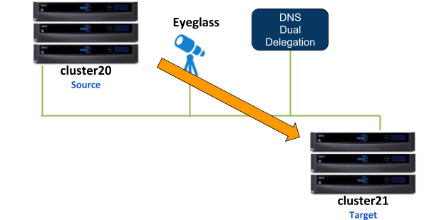
As an example for this IP Pool failover setup, dual non-overlap IP Pools are configured on the source cluster and on the target cluster. All IP Pools are assigned to the System Access Zone.
SMB share
- s-smb01 is configured on Source cluster
SMB shares are managed through Microsoft DFS server.
NFS export:
- /ifs/data/s-nfs01 export is configured on Source cluster
SyncIQ Policies:
SyncIQ Policies are configured as follow:
| SyncIQ Policy | Data | From | To |
| s01-t01-synciq01 | SMB | Source | Target |
| s01-t01-synciq02 | NFS | Source | Target |
Policy - Pool Assignment
This table illustrates the SyncIQ Policies to Pools assignments:
| From | To | Policy | Data | ||
| Cluster | Pool | Cluster | Pool | ||
| Source | Pool 1 | Target | Pool 1 | s01-t01-synciq01 | SMB (DFS) |
| Source | Pool 2 | Target | Pool 2 | s01-t01-synciq02 | NFS |
Policy - Pool Mapping Diagram
The following diagram shows the IP Pools and Policies mapping setup between Source and Target clusters
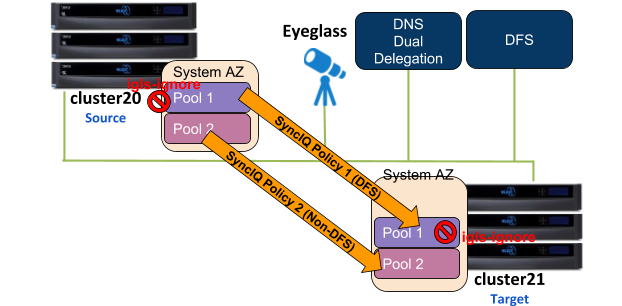
The igls mapping hints including igls-ignore also need to be configured for this dual IP Pool setup.
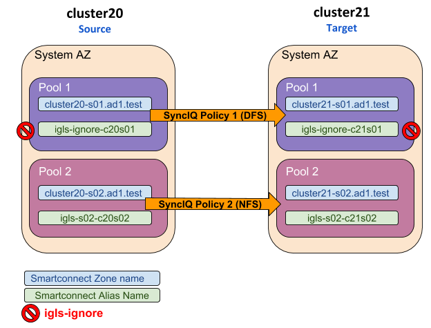
Based on that diagram, the following is the example of the igls and igls-ignore hint mappings:
That configuration also can be seen in the following diagram:
Configuration Steps:
- Configure the required igls and igls-ignore mapping hints for all the Pools in the Access Zone.
- Verify the DR Dashboard - Zone Readiness that Network Mappings have been configured correctly.
- Configure the Advanced Network Mapping to map the Policies to the Pools as specified in the Policies - Pool Mapping table. To assign the policy to the pool, from DR Dashboard - Pool Readiness click Advanced Network Mapping button. Eyeglass will prompt a warning for configuring this Advanced Network Mapping: “Warning: Policy mapped to pool can be failed over using only Pool Failover option. Click OK to continue.” Click OK to continue.

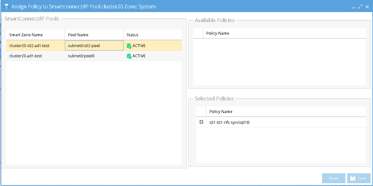
- Select the Access Zone for specific Source-Target Cluster Pair to configure and then click Next button. In the Assign Policy to SmartConnect/IP Pool configuration window, select a SmartConnect/Pool from the list and then drag and drop the correct policy from the Available Policies section (under the Policy Name column) to the Selected Policies section. Click Save to save the modification for each policy as it is selected.
IMPORTANT: Please ensure the policies are mapped to the correct pools.
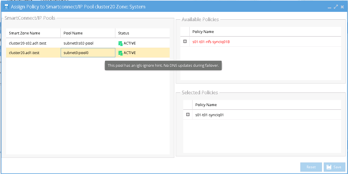
IMPORTANT: Policies where the Eyeglass Configuration Replication mode is set to DFS will only be displayed for selection when the Pool has an igls-ignore hint.
Example:
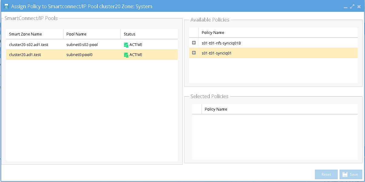
Once assigned we can see the following mappings:
The IP Pool that has the igls-ignore alias is listed in the SmartConnect/IP Pools section with description:”The pool has an igls-ignore hints. No DNS updates during failover”. This description can be seen by hovering mouse over that IP pool area.
- Verify that in DR Dashboard - Pool Readiness the DR Failover Status is showing no error.
Example:
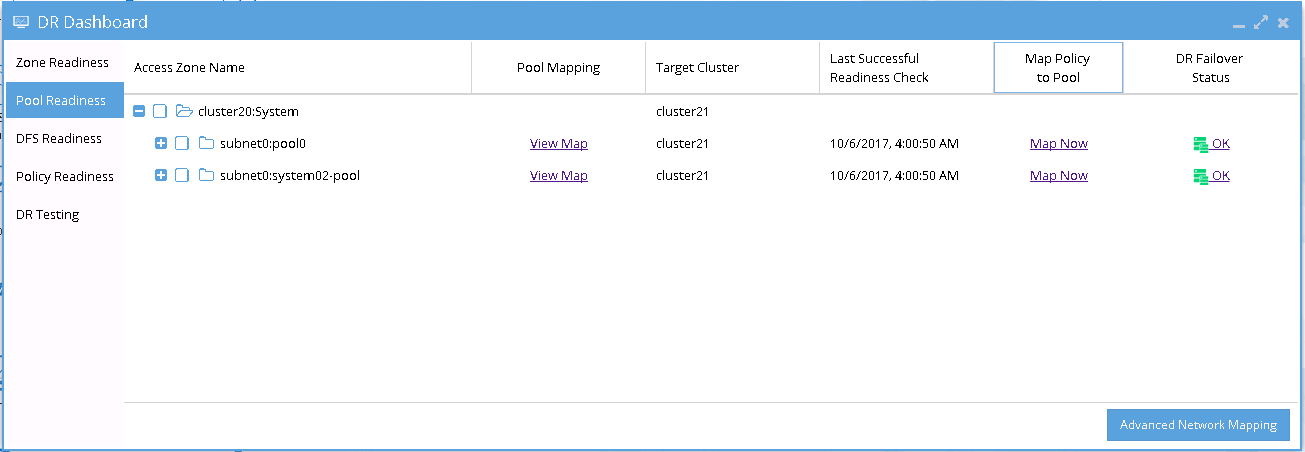
- SmartConnect/IP Pool Failover
To perform IP Pool failover, in the DR Assistant Failover Wizard select failover type as SmartConnect/IP Pool Failover, and then select IP pool to be failed over .
Example:
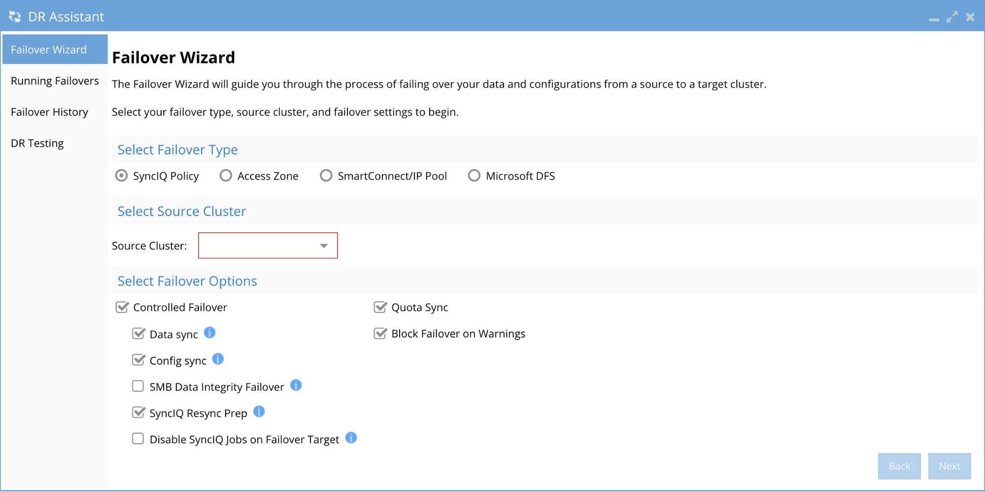
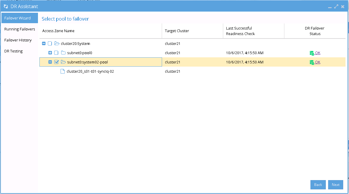
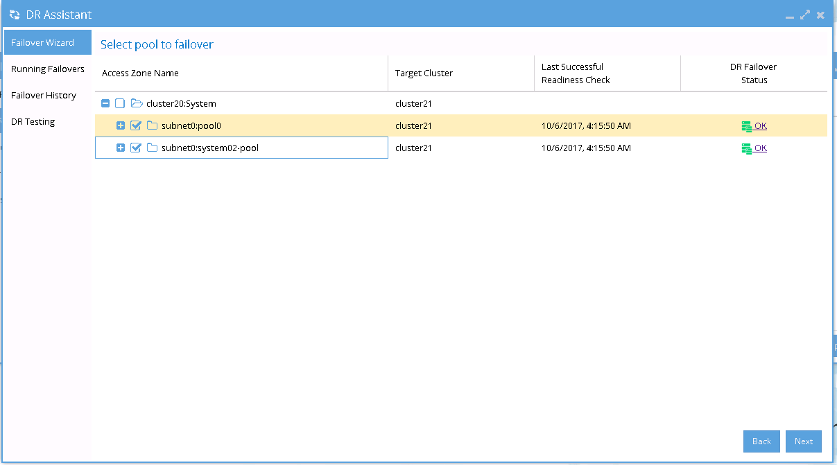
- If we want to failover all the pools within the Access Zone with this IP Pool failover, select all the pools from the list of Select pool to failover.
Example:
- After Pool failover job has completed, we can see which pool has been failed over from the Pool Readiness - DR Failover Status.
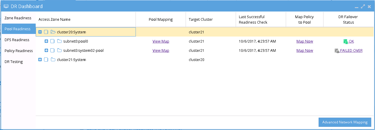
Example of IP Pool Failover
The following examples illustrate the changes of the SmartConnect zone names and alias names for IP Pool failover in the following sequences:
- Pool Failover Source (Pool 2) to Target (Pool 2)
- Pool Failback Target (Pool 2) to Source (Pool 2)
Pool Failover Source (Pool2) ⇒ Target (Pool2)
The following table and diagram illustrate the SmartConnect zone names and alias names after performing Failover from Source (Pool 2) to Target (Pool 2).
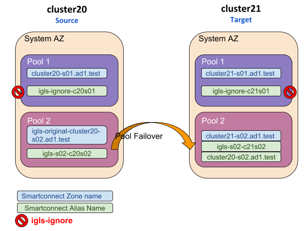
Pool Failback Target (Pool2) ⇒ Source (Pool2)
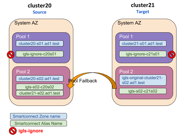
The following table and diagram illustrate the SmartConnect zone names and alias names after performing Failback from Target (Pool 2) to Source (Pool 2).
