Fan-In IP Pool Failover
Prerequisites
- The target cluster must have a dedicated IP pool for each source cluster IP pool as a failover target. Example 3 source clusters with 1 IP each will require the target cluster to have 3 IP pools.
Fan-In configuration Diagram
The following diagram gives an example of Fan-In configuration topology
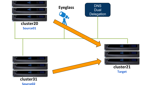
This configuration consists of 3 clusters, 2 of them are the source clusters and third one is the target cluster. For this example:
- Cluster20 is the Source01 Cluster
- Cluster31 is the Source02 Cluster
- Cluster21 is the Target Cluster
For the IP Pool failover setup, dual non-overlap IP Pools are configured on the source clusters and four non-overlap IP Pools are configured on the target cluster. All IP Pools are assigned to the System Access Zone.
SMB shares
- source01-smb01 is configured on Source01 cluster
- source02-smb01 is configured on Source02 cluster
SMB shares are managed through Microsoft DFS server.
NFS exports:
- /ifs/data/source01-nfs01 export is configured on Source01 cluster
- /ifs/data/source02-nfs01 export is configured on Source02 cluster
SyncIQ Policies:
Configured the following SyncIQ Policies:
| SyncIQ Policy | Data | From | To |
| s01-t01-synciq01 | SMB | Source01 | Target |
| s01-t01-synciq02 | NFS | Source01 | Target |
| s02-t01-synciq03 | SMB | Source02 | Target |
| s02-t01-synciq04 | NFS | Source02 | Target |
SyncIQ Policy to Pool Assignments
The following table illustrates the SyncIQ Policies to Pools assignments
SyncIQ Policies - Pools Mapping Diagram
The following diagram shows the SyncIQ Policies and Pools mapping setup
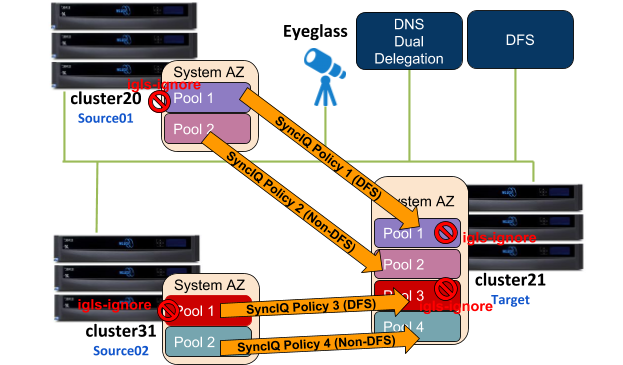
The igls mapping hints including igls-ignore also need to be configured for this dual IP Pool setup.
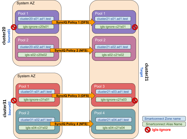
Based on the above diagram, the following is the example of the igls and igls-ignore mapping hints:
The mapping also can be seen in the following diagram:
Configuration Steps:
- Configure the required igls and igls-ignore mapping hints for all the Pools in the Access Zone.
- Verify from DR Dashboard - Zone Readiness that Network Mappings have been configured correctly.
- Configure the Advanced Network Mapping to map the Policies to the Pools as specified in the Policies - Pool Mapping table. To assign the policy to the pool, from DR Dashboard - Pool Readiness click Advanced Network Mapping button. Eyeglass will prompt a warning for configuring this Advanced Network Mapping: “Warning: Policy mapped to pool can be failed over using only Pool Failover option. Click OK to continue.” Click OK to continue.

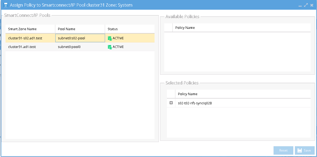
- Select the Access Zone for specific Source-Target Cluster Pair to configure and then click Next button. In the Assign Policy to SmartConnect/IP Pool configuration window, select a SmartConnect/Pool from the list and then drag and drop the correct policy from the Available Policies section (under the Policy Name column) to each pool. Click Save to save the modification. Note: please ensure the policies are mapped to the correct pools.
Example:
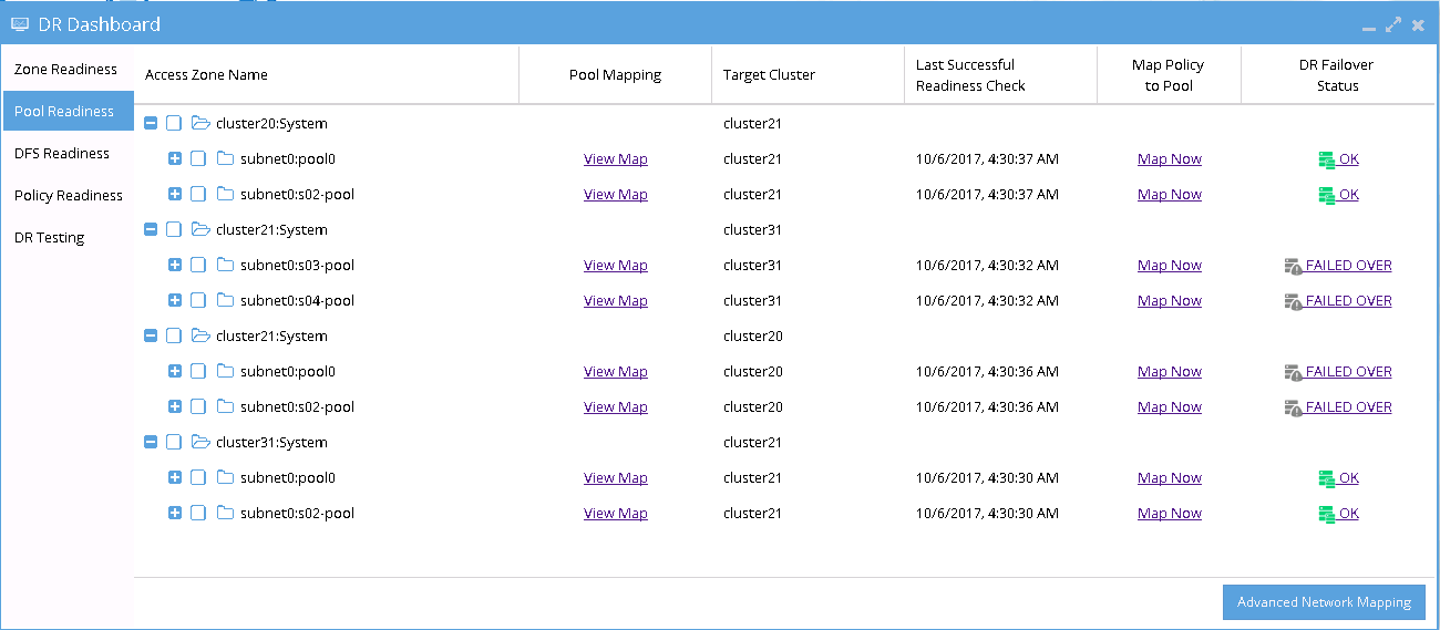
- Verify that the SmartConnect/IP Pool Failover Readiness Status is showing no error.
Example:
- SmartConnect/IP Pool Failover.
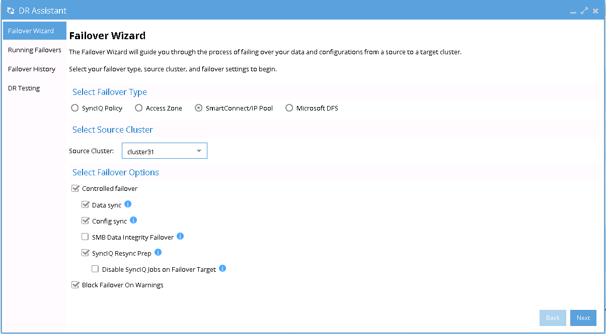
To perform IP Pool failover, in the DR Assistant Failover Wizard select failover type as SmartConnect/IP Pool Failover, and then select IP pool to be failed over.
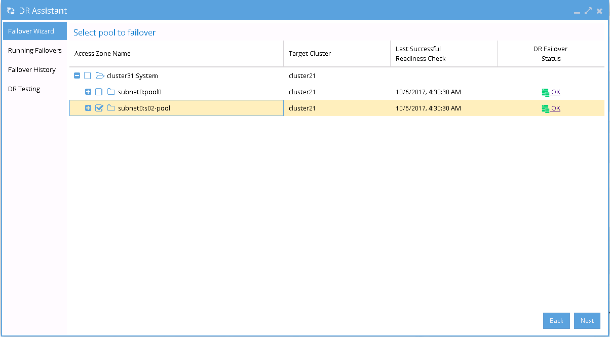
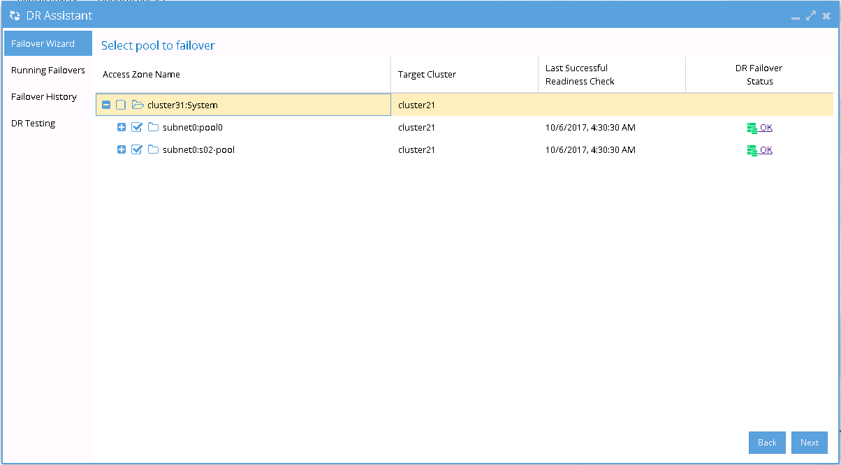
- If we want to failover all the pools within the Access Zone with this IP Pool failover, select all the pools from the list of Select pool to failover.
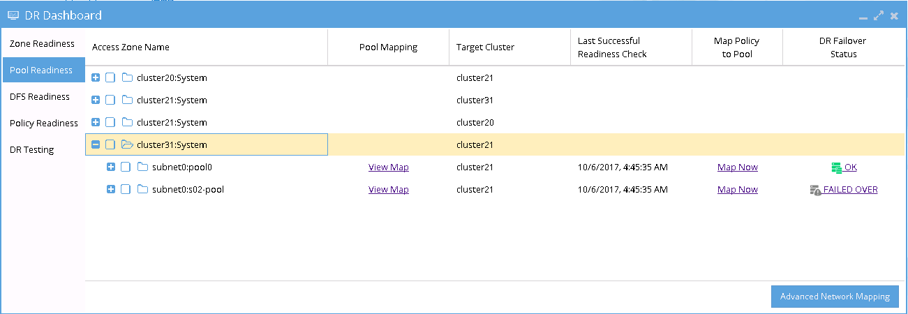
- After Pool failover job has completed, we can see which pool has been failed over from the Pool Readiness - DR Failover Status.
Example of Pool Failover
The following examples illustrate the changes of the SmartConnect zone names and alias names for IP Pool failover in the following sequences:
- Pool Failover Source01 (Pool 2) to Target (Pool 2)
- Pool Failover Source02 (Pool 2) to Target (Pool 4)
- Pool Failback Target (Pool 2) to Source01 (Pool 2)
- Pool Failback Target (Pool 4) to Source02 (Pool 2)
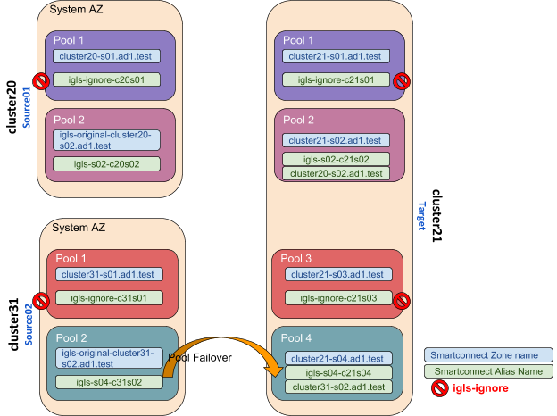
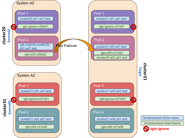
Pool Failover Source01 (Pool 2) ⇒ Target (Pool 2)
The following table and diagram illustrate the SmartConnect zone names and alias names after performing Failover from Source01 (Pool 2) to Target (Pool 2).
Pool Failover Source02 (Pool 2) ⇒ Target (Pool 4)
The following table and diagram illustrate the SmartConnect zone names and alias names after performing Failover from Source02 (Pool 2) to Target (Pool 4).
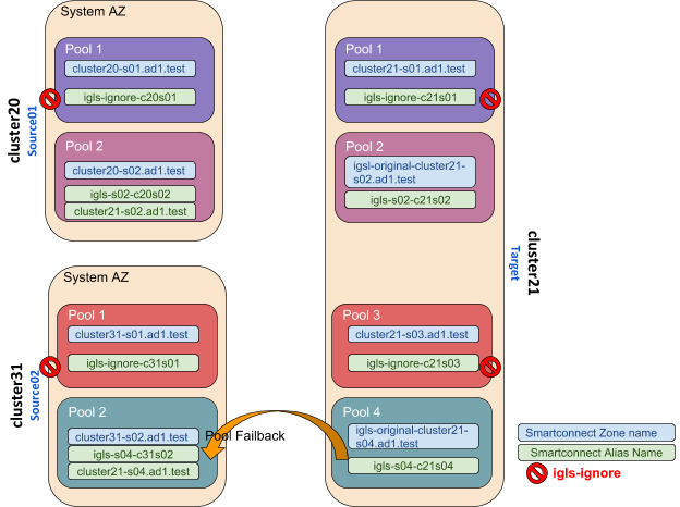
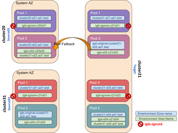
Pool Failback Target (Pool 2) ⇒ Source01 (Pool 2)
The following table and diagram illustrate the SmartConnect zone names and alias names after performing Failback from Target (Pool 2) to Source01 (Pool 2).
Pool Failback Target (Pool 4) ⇒ Source02 (Pool 2)
The following table and diagram illustrate the SmartConnect zone names and alias names after performing Failback from Target (Pool 4) to Source02 (Pool 2).
